
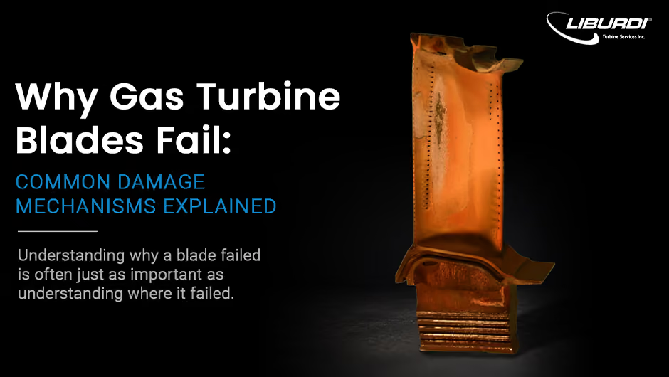
A cracked turbine blade rarely tells the whole story.
Two blades can fail in nearly identical locations for completely different reasons. One may have reached the end of its service life. Another may point to an underlying operational issue that could continue damaging future components if left unresolved.
Understanding why a blade failed is often just as important as understanding where it failed.
The root cause of the damage influences the corrective actions needed to reduce the likelihood of repeat failures.
Gas turbine blades operate in some of the harshest conditions found in industrial equipment. They are exposed to extreme temperatures, high centrifugal forces, repeated startup and shutdown cycles, and a constant stream of hot combustion gases. Over thousands of operating hours, these conditions gradually change the material itself.
While every failure investigation is unique, most blade damage can be traced back to a relatively small number of degradation mechanisms. Recognizing these mechanisms is the first step toward understanding what happened and why.
The way a gas turbine operates has a significant influence on how its components degrade.
A turbine that cycles on and off frequently may experience different damage than one operating continuously at base load. Environmental conditions, fuel quality, cooling effectiveness, and operating temperatures also influence component life.
Although every investigation is different, most gas turbine blade failures involve one or more of the following degradation mechanisms.
Every startup and shutdown cycle causes turbine components to expand and contract.
Over time, these repeated temperature changes generate stresses within the material. Eventually, small cracks begin to form.

Thermal fatigue is particularly common in turbines operating in cyclic service, such as power generation units that start and stop to meet peak electrical demand.
Engineers evaluate more than the presence of a crack. Its location, orientation, depth, and progression help determine whether the damage is isolated or symptomatic of a broader operating issue.
Engineer Insight A crack may be the visible symptom, but it rarely explains the underlying cause. Understanding how the crack formed is what determines the most appropriate path forward.
Hot-section components rely on protective coatings and oxide layers to shield the underlying alloy from extreme temperatures.
Over time, these protective layers gradually deteriorate.
As coatings degrade, the underlying alloy becomes increasingly exposed to the operating environment. Material loss accelerates, component temperatures rise, and service life can decrease significantly.
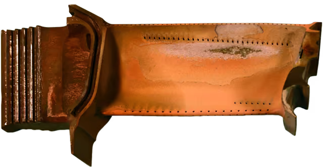
Even relatively small increases in metal temperature can dramatically increase oxidation rates, making coating condition one of the most important factors affecting hot-section durability.
Surface discoloration may be the only visible indication of degradation, while more significant damage develops beneath the coating.
Engineer Insight Two components may appear similar during inspection yet have very different levels of oxidation beneath the surface.
Not every failure occurs suddenly.
When turbine blades operate for extended periods at elevated temperatures, the material can slowly deform under sustained load through a process known as creep.
Because rotating blades are continuously subjected to high centrifugal forces, creep is most commonly found in rotating hot-section components.
The damage develops gradually. Microscopic voids begin forming along grain boundaries before linking together to create cracks. By the time creep becomes visible during inspection, significant internal degradation may already exist.
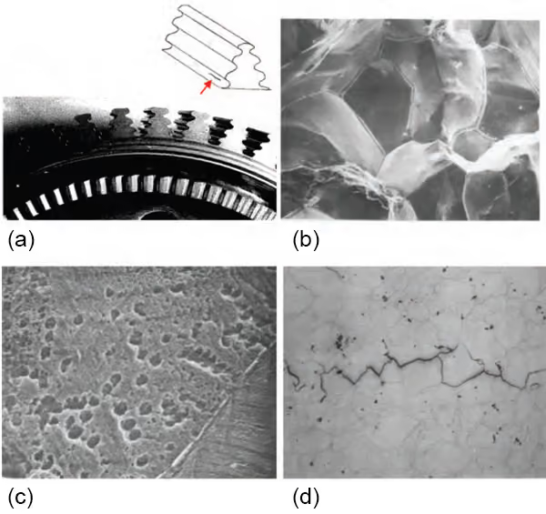
Metallurgical examination is often required to identify creep damage before it becomes obvious during visual inspection.
Engineer Insight Components with nearly identical external appearances can exhibit dramatically different levels of creep damage internally.
Gas turbine blades can also be damaged by particles moving through the engine.
Foreign Object Damage (FOD) occurs when debris impacts a blade surface. Depending on the size and velocity of the object, the damage may range from minor surface dents to deep cracks or fractured airfoils.
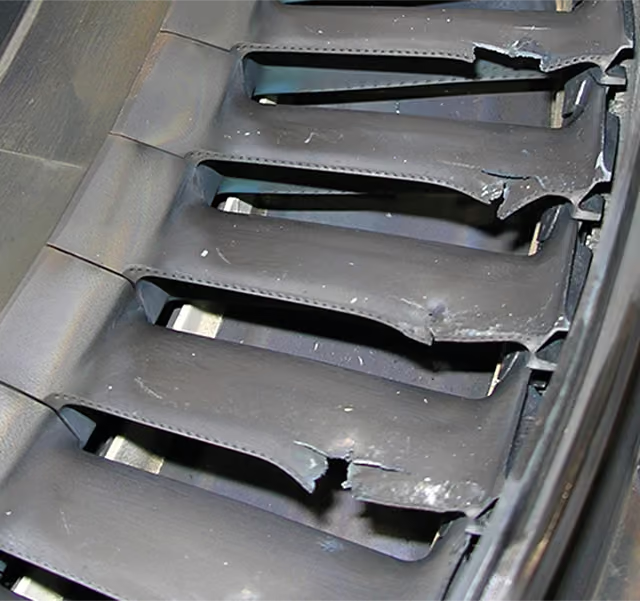
Smaller particles create a different form of degradation known as erosion.
Repeated particle impacts gradually remove material from blade surfaces, particularly along leading edges and the pressure (concave) side of the airfoil. Over time, erosion can alter blade geometry, reduce aerodynamic efficiency, and shorten component life.
Understanding whether damage resulted from a single impact or long-term erosion helps determine the underlying cause and guide the appropriate corrective actions.
Some of the most aggressive forms of blade degradation originate from the operating environment.
Salt, sulfur, and other contaminants can react with hot-section surfaces and disrupt the protective oxide layers that normally shield turbine components.
This process, commonly known as hot corrosion, can consume material much faster than oxidation alone.

Hot corrosion is frequently associated with marine environments, contaminated fuels, or poor process water quality. Without proper controls, significant material loss can occur in a relatively short period of time
Engineer Insight Operating environment can have as much influence on component life as operating hours.
One of the biggest challenges in failure analysis is that similar damage does not always originate from the same mechanism.
A crack near the blade tip does not automatically indicate thermal fatigue.
Likewise, material loss along the leading edge does not always point to erosion.
Many degradation mechanisms produce similar visual symptoms but require very different corrective actions.
Determining the difference often requires combining visual inspection with nondestructive testing, dimensional inspection, operating history, and metallurgical analysis.
Understanding why a component failed is often the difference between correcting a symptom and solving the underlying problem.
Identifying a failure mechanism involves much more than visual inspection.
A comprehensive failure analysis may include:
Identifying a failure mechanism involves much more than visual inspection.
A comprehensive failure analysis may include:Each technique contributes a different piece of the overall picture.
Together, they help engineers determine not only what failed, but why it failed.
Damage does not automatically mean a component must be replaced.
In many cases, the answer is:
It depends.
Repair decisions are based on much more than visible damage.Engineers consider factors such as:
A component that initially appears beyond repair may still be recoverable.
Conversely, relatively minor visible damage may indicate degradation that makes repair inadvisable.
The underlying failure mechanism provides the information needed to determine the appropriate corrective actions.
A damaged turbine blade rarely fails for a single reason.
Operating conditions, temperature, loading, environment, material condition, and previous repairs all leave evidence behind.
The challenge is interpreting that evidence correctly.
Failure analysis helps identify not only what failed, but why it failed, allowing operators to implement corrective actions, improve reliability, and reduce the likelihood of repeat failures.
Whether a component can be repaired, requires replacement, or points to a larger operational issue often depends on understanding the complete picture.
If you're evaluating damaged turbine components or investigating recurring failures, a comprehensive failure analysis can provide answers that extend well beyond the visible damage.