
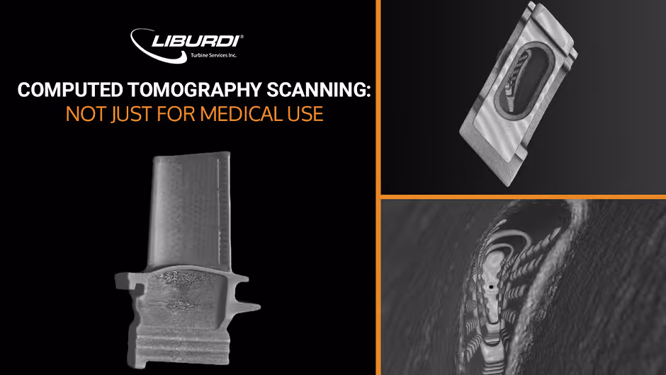
For 45 years, Liburdi Turbine Services has extended the life of gas turbine components using Liburdi's in-house technologies. Computed Tomography (CT) Inspection ensures continued reliability and safe life extension of repaired components. CT technology is an enabling tool in the Liburdi suite of capabilities for extending the life of rotating components safely and robustly.
As part of Liburdi’s support for customer hot section inspections, CT scanning provides unparalleled visibility into the internal geometry of turbine blades and vanes, detecting wall thinning or defects invisible to ultrasonic testing.
Ultrasonic thickness (UT) inspection is traditionally used to measure the wall thickness of internally cooled gas turbine blades. Ultrasonic wall thickness inspection measures the time ultrasonic pulses travel through the material and back to the sensor. UT inspections are performed at specific points around the airfoil of the turbine blade.
UT inspection, however, has technological limitations in obtaining an accurate measurement for gas turbine blades with complex internal and external geometries. The drawbacks of UT inspection are most apparent with turbine blades which have undergone multiple repair cycles. Additionally, UT inspection of specific points does not lend itself to a complete understanding of the internal geometry and potential defects between established measurement locations.
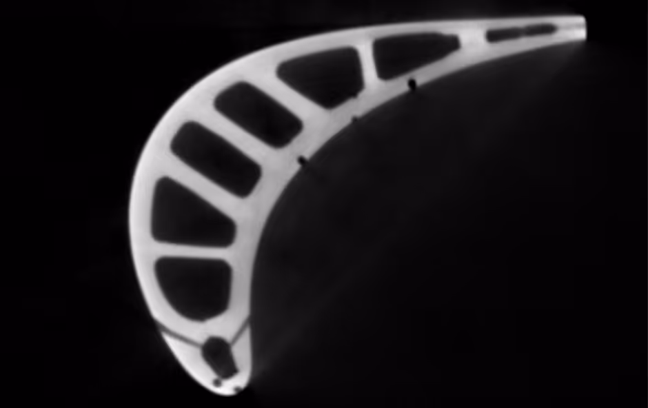
To overcome the limitations of UT inspection, Liburdi performs complex inspections using computed tomography (CT) X-Ray technology. The ability to inspect a cross-section of the gas turbine blade is crucial to ensure that no point of the turbine blade is subjected to thinning or other defects that may cause a failure in service.
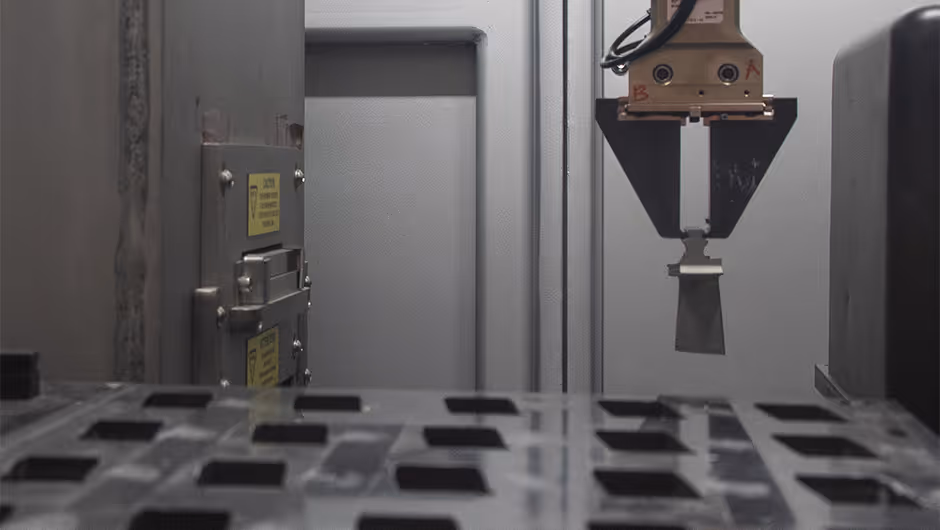
Liburdi’s CT scanner uses a Linear Diode Array (LDA) sensor to acquire multiple images from each slice as the gas turbine blade continuously rotates in the X-Ray fan beam. The fan beam offers improved high-quality results as opposed to the conventional cone beam by reducing the noise and scatter caused by the dense nickel alloy. The computer uses these scans to reconstruct an image of the tomographic slice showing the internal geometry.
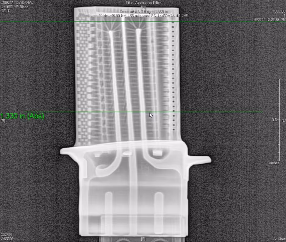
Extracting 2D and 3D inspection scans provides easy and prompt identification of critical internal structures in specific areas of interest. The slice technique allows a more detailed evaluation of internal casting geometry.
This digital scanning process allows Liburdi to examine parts at a higher level of scrutiny, which results in more confidence in the inspection results.
To see how Liburdi’s decades of expertise have helped extend gas turbine component life, contact info@liburditurbineservices.com to start a conversation about how we can support your next hot section inspection.